Nebitype NTC Coolant system
The Nebitype uses a water pump to circulate coolant:
- from the coolant tank
- through a bypass valve
- through the mould
before returning the coolant to the tank at the right rear of the machine base.
The only role of the coolant system is to cool down the mould (#1206, #1207, #1208, #1209) which will help solidify the 'tang' of the slug.
(The 'tang' portion of the slug is cast inside the mould, whilst the face of the slug is cast inside the mats, which are held in the stick.
The stick and mats have no cooling system, and this would generally not be required unless there were a vast amount of continuous casting occurring.
In normal operation, mats would be changed between casting cycles, giving them ample time to lose any heat from the casting process.
The only routine continuous casting to occur would be the blank slugs which are used to underpin the face of large slugs - which are completely cast inside the mould and will be cooled by the coolant system.)
The Coolant Tank (#509)
The Coolant tank of the Nebitype holds 24.6 litres (6.5 US gallons) of coolant which is water mixed with a water-soluable oil at approximately 1 litre of coolant to 23.6 litres of water. The coolant tank is built into the back of the base of the machine and has a small removable lid at the top with two cutouts for the coolant return, one from the mould and one from the Water Control valve. The tank has an isolating tap inside the cover on the right base of the machine which can be used to drain the tank if necessary. The coolant tank is at room temperature and there is no active chilling of the coolant other than than which would occur from radiation from the back of the machine.
The tank should occasionally be cleaned (see Nebitype Maintenance) to remove the inevitable debris which will distill at the bottom of tank. This is probably only required when changing the coolant or immediately after moving the machine as the settled material is likely to be stirred up by both activities. The cover should be left on the tank except for when checking the flows from the mould and Water control valve.
The Water Control (Bypass) Valve (#2804)
The Water Control (Bypass) Valve is located on the front of the machine, to the right of the elevator. It is marked with + and - symbols to indicate the amount of flow through the mould. Increasing the flow will supply more cooland to the mould which would enable it to cool down the cast slug slightly faster. In actual operation, the Water Control Valve does not directly control coolant to the mould, but instead controls the amount of coolant that is returned to the coolant tank. As the Mould and the Water Control Valve are both connected to a common T-Block (#2517), increasing the flow through the valve to the tank return hose (#2448) will in turn decrease the flow through the mould.
Hoses
The hoses for the coolant come in sections which are screwed into each other, ensuring cleaning can be performed and parts can be serviced. With the exception of the ends that deliver into the coolant tank, all hose ends have screw fittings. The sections are separated:
- At the water pump,
- At the ends of the short hose sections to the water pump,
- At the T-Block,
- At the Mould (via the hose stems),
- Prior to he mould (where the coolant pipes emerge from the body of the machine),
- Either side of the Water Control valve.
Water Pump (#1113)
The water pump is a vane pump, and only operates when the machine is running through its cycle.
(Note that coolant is not required to cool the mouthpiece or any other part of the machine, only the mould, which is only in use during casting.)
Vane pumps are reliable and have the advantage of a constant flow without pulsation and have low leakage.
The coolant pump is driven via a pulley (#2441) and belt (#2439) connected to a pulley (#2425) on the main worm shaft.
A secondary role of the pump is to provide a small amount of drag to the main worm shaft in order to bring the machine to a halt at the end of a cycle.
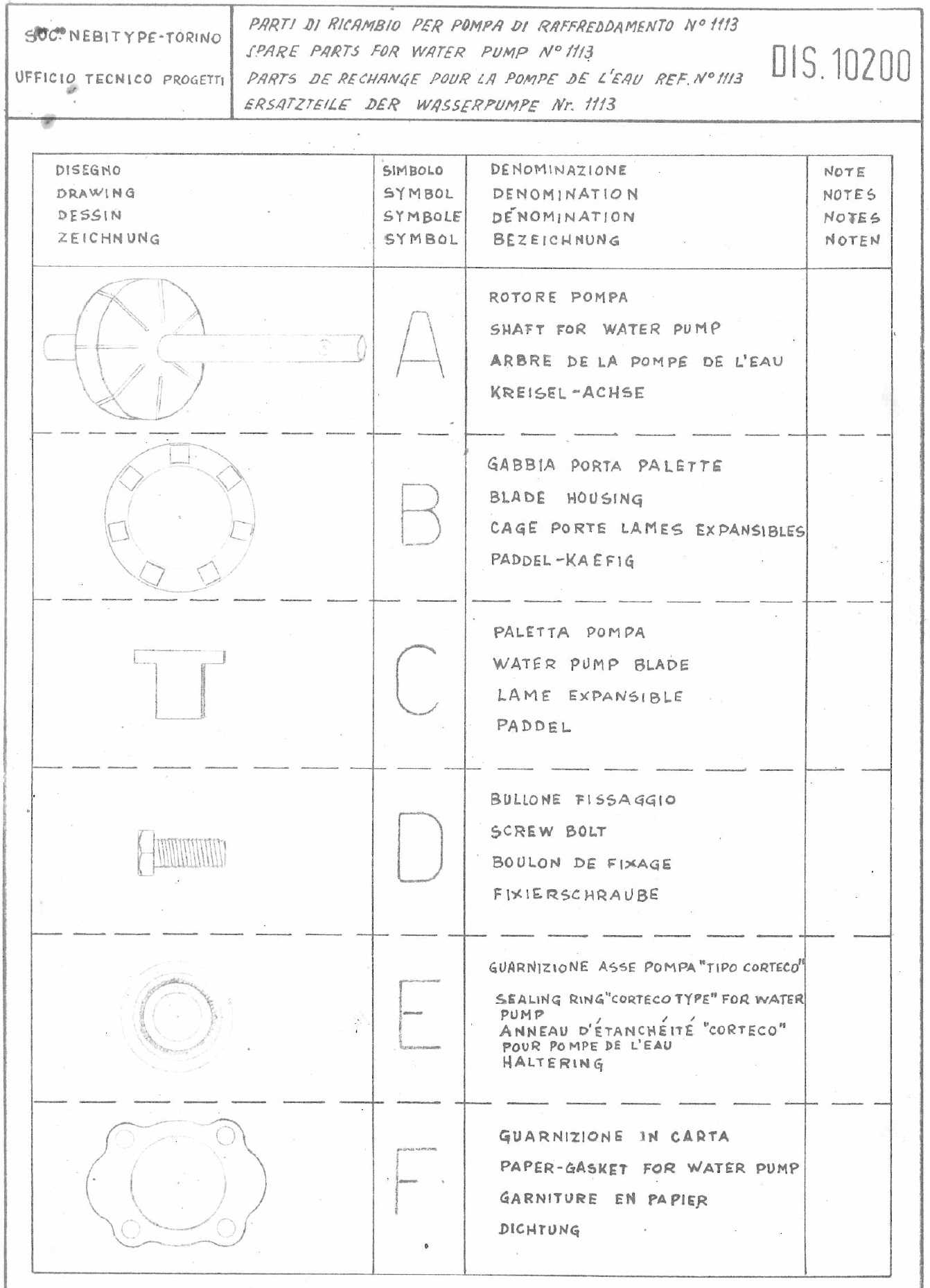
A breakdown of the parts of the water pump can be found here.
Pump Maintenance
Pump Leaks
Due to the age of the machine, coolant leaks may be detected from the shaft at the top of the pump.
There is a fluid seal under the cover at the top of the pump, held down by two small bolts, which is likely to be failing if this is the case.
Replacing the seal is likely to require pump disassembly as the original seal has a steel body which will likely need to be driven out with a punch from inside the pump body.
Some pitting may be evident on the pump shaft, which may need to be addressed for a complete seal.
Pump Disassembly
The Pump is fairly straight forward to disassemble, with four small bolts holding the top and bottom sections together.
The Pump should be removed from the machine to do this, and the halves of the pump should be separated carefully, over a clean surface, to ensure the vanes don't get lost.
Belt Tension
The Pump is mounted on a bracket (#2017) which is bolted to the body of the machine inside the panel at the right front of the base of the machine.
Tension is manually applied to the pump and then the bolt tightened to maintain the tension. There are no other tension adjustments.
The coolant pump belt tension does not need to be excessive as the pump load is not high.
Excessive tension is likely to damage the pump over time.
Flow Issues
Where you suspect the coolant is not flowing through the system properly the best option may be to unscrew the hoses at various points and run the machine for a few seconds before stopping it.
PRIOR TO OPERATING THE MACHINE you should unscrew and remove the microswitch assembly plug (#E10013) from the machine which should ensure that the plunger will not be activated.
A second safeguard would be to disconnect the plunger from the operating cam, however this is unlikely to be achieveable if the type metal is not in a liquid state.
(This is also why disconnecting the plunger from the cam is a good idea prior to shutting down the machine.)
Hoses can be cleared with compresser air, however it's probably unwise to direct high pressure air into the pump or the water control valve.
The Mould
The mould is a block of stainless steel with a 6 or 12pt slot in it (depending on the mould chosen) with an internal channel to permit coolant water to flow through it. The mould is mounted via two cheese head allen screws to the elevator and connected to the coolant hoses by two Hose stems, a short (2432) and long (2457) stem. The short stem is fitted to the left (lower) of the ports in the mould.
General Maintenance
There are a few routine maintenance operations that should be undertaken:
- Checking coolant levels (A dipstick would be the simplest method; just calibrate it after filling the machine).
- Cleaning the coolant tank and replacing the coolant.
- Cleaning the coolant lines (compressed air through all sections EXCEPT the water control valve and water pump.)
- Checking the coolant system for leaks.
- Verifying coolant flow by observing flow from the two hoses which empty into the coolant tank when the machine is operating.
- Checking the coolant pump belt tension.
