Nebitype NTC Lubrication
This document outlines the oiling for the Nebitype NTC. Where possible, part numbers (specific to the NTC parts guide) will be used, along with an indicative location. A medium grade of oil, like a standard SAE 30 4-Stroke non-synthetic mower oil, should be used.
The Oil Tank
The Nebitype contains a small oil tank (#2043) inside the top of front base of the machine. This is accessed by lifting the front trimmings tray (#1021) and removing the reservior plug (#2628). The tank does not store a great deal of oil, so it will probably need to be refilled before the start of work as it will likely have been depleted while the machine was idle. The tank is connected to a series of small pipes which drip oil via gravity into various oiler points along the cam shaft.
Oil Points
The rest of the Nebitype needs to be oiled manually, and the oiling ports are:
- The pivot at the top of the metal feeder. (Noting that the NTC model I have has an mechanical feeder, not an electronic one).
- The pivots for the Pot Cover (#511), the Pot Cover door (#2013) and Protection Guard (#521).
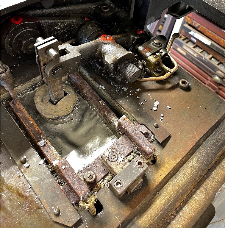
- The Slide Lever Pivots(#518)
- The base joint of the Slide Lever (near #2410),
- The 'shoulder' of the Slide Lever (at screw #2653), and
- The end of the Slide Lever (at screw #2613)
- Both sides of the Elevator Slide Bell Crank (#1005)
- The area where the Stick Carrier (#525/#527) slides on the Elevator slide. Oil the mating surfaces as there is no oil port at this location
- Inside the Pot Cover Oil points in red below (#2013)
- The Plunger Pivot x 2 (#2206)
- Main lever from the Cam x 2
- The metal feeder actuating pivot
- Inside the left hand cover at the base of the machine
Grease Cups
There are two grease cups (#2632#506 Plate 3). Access to these grease cups is available to the double
jointed via the top stand cover (#517 Plate 2). The grease cups are difficult to remove (There's one on
either side of the Holding Device Bracket) but they're even harder to reinstall. It may pay to advance the machine
until the elevator is at the top of its motion to give more access.
Given the difficulty in accessing these areas it was unsurprising to me to find that the right hand cup (the easiest
to get to) was empty and the left hand cup was unadjusted and had the consistency of leather. Attempting to replace
the left hand grease cup is even more difficult that removing it as there is very limited access and I dropped it
into the machine, and have not seen it since...
These should filled with a light grease as per the manual's documentation.
As noted, unless the machine is in production it should be oiled/greased prior to starting work on the machine.
Ideally, any oiling to be performed around the Pot should be done while the machine is cold to limit any (albeit unlikely) possibility of combustion from a spillage.
Spilt oil should be wiped off surfaces.