Nebitype Power
Note that this page is only partly completed and is bound to contain errors. It will be updated as, if, and when time allows. And I'm no electrician!
No information herein should be construed as accurate, and all electrical connectivity should be verified by a licensed electrical tradesperson prior to using the machine. The Nebitype machine uses dangerous voltages for both its mechanical operation and its safety mechanisms, so the machine should be properly earthed and never run with covers open. (It was definitely not intended to be run with the covers open, and later models had better cabling and an interlock to prevent the control panels from opening unless mechanically isolated.)
The Nebitype machine came a couple of different versions, with differing power configurations. The two main differences were:
(1) 115V AC or 240V AC, and
(2) Single or Three phase motor.
The 240V machines I've seen have a small 115V step down transformer which appears to have run at least part of the control circuitry. (My NTC has a dead 115V step down transformer, and the pot temperature control was replaced with a PID controller which runs the elements at 240VAC.) The step down transformer is fairly low wattage and would never have handled the power required by the elements or the motor.
The Motor
There is a single motor in the Nebitype which controls all movement via a vertical worm drive shaft and a horizontal cam shaft.
The motor only runs when the machine is in a casting cycle, the rest of the time it is powered down. The machine came with either
a single or three phase motor, and most of the documentation I have is for 3 phase motors. My machine has a single phase motor.
The Motor on my NTC is Single Phase, 50Hz, 1HP, 230VAC. The Badge on it also notes that the manufacturer was "Cograf/Milano",
(with less information on the web than Nebitype..), the model was 1020 and the type was "PFCM 6/4".
also
Contactors
Heating element contactors
The pot and mouthpiece element contactors are activated by their respective temperature controllers. The original NTC Pot element control consisted of a temperature meter and two control knobs, the needle on the meter showing the pot temperature (from the thermocouple in the pot) and the two knobs setting the on/off temperatures for the pot heating elements.
The mouthpiece temperature control varies between models, with some having no feedback and relying on a 'duty cycle' adjustment.
The casting cycle contactor
The contactor is engaged by the Start button and is disengaged by the end-of-cycle microswitch OR by manual activation of the Stop switch.
The Stop switch can be used at any point in the cycle, however it could be unwise to stop the machine at the point the plunger is descending.
Additionally, the machine should be run through a complete cycle prior to powering down.
The contactor provides a few functions:
- Stops the machine at the correct point at the end of the cycle (via the cycle-end switch - unless the repeat casting switch is on).
- Ensures the machine will not complete a cycle after a brief power loss and cast when the machine is unattended.
- Ensures the machine will not complete a cycle after a long power outage when the pot is full of solid type metal.
- Livens various parts of the system which are required only during the cycle (i.e. the Motor and the Microswitch safety circuits to prevent unsafe casting).
The contactor also has a 'thermal relay', (i.e. a motor starter) which will trip the contactor if the motor draws too
much current (i.e. in the event of a jam or if the voltage to the motor was low due to some power supply issue.)
The motor starter protects the motor windings from burning out and should never be disconnected or bypassed.
Note also that the Nebitype is fitted with a torque limiter, which should prevent the motor from stalling,
however if this is poorly adjusted, worn, or there is some jam at the driven pulley the motor could still stall.
Safety Switches
There are a number of safety switches on the machine, although sometimes owners have bypassed them to save time in debugging the issues with the machine. The switches are:
- The three microswitches in the stick holder, two PIN microswitches which engage with the pins in the stick and are actuated by the successful lining-up of the stick, mould and mouthpiece, and a MAT microswitch which will engage with at matrix in the middle position of the stick to indicate that matrices are present. All three switches must be closed to cast.
- The Protective cover in front of the mouthpiece. This cover must also be closed or the machine will not cast.
A cable running through the base of the microswitch assembly connects the POT and MAT microswitches to each other, in series.
The switches control the engagement of the Pump Latch solenoid. If any one of the switches is in the open position, or if the microswitch assembly plug is removed from the socket, or there is a broken wire or connection then the pump latch will not activate.
It is good practice to remove the microswitch assembly plug from the machine when working on it to ensure there is no risk of a 'squirt'.
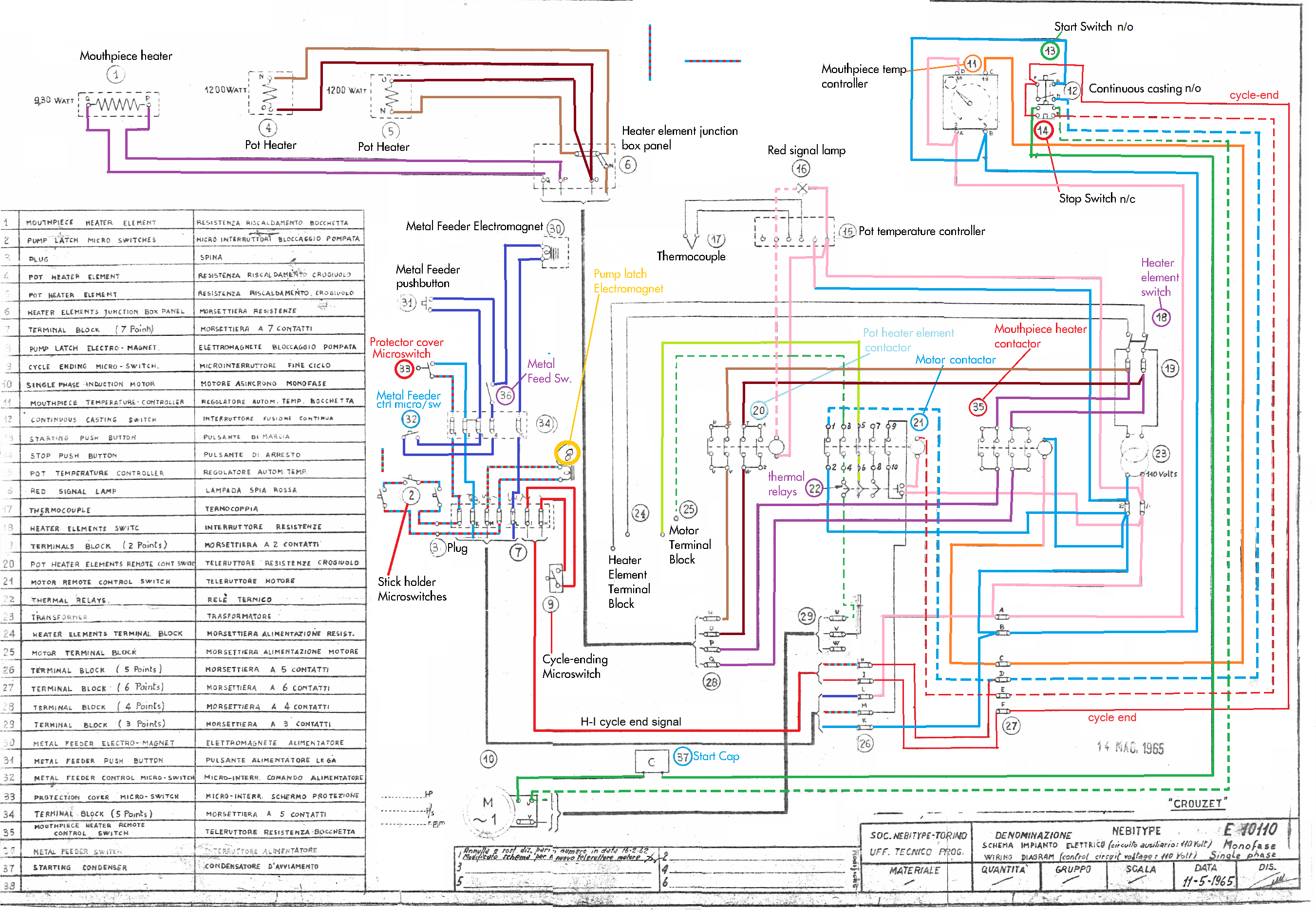
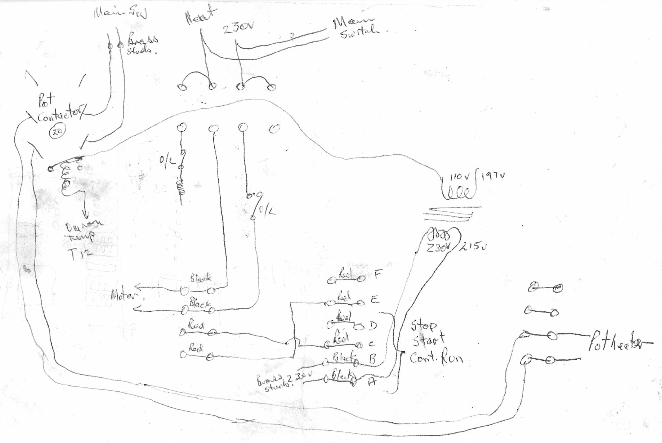
In an effort to diagnose some electrical pathways I 'colour-coded' the Nebitype single phase wiring diagram, included immediately below.
This is most definitely not a work of art, nor a complete diagram (due to the quality of the original scans), however it may provide
sufficient information to enable a single-phase nebitype owner to trace at least part of the machine's connectivity.
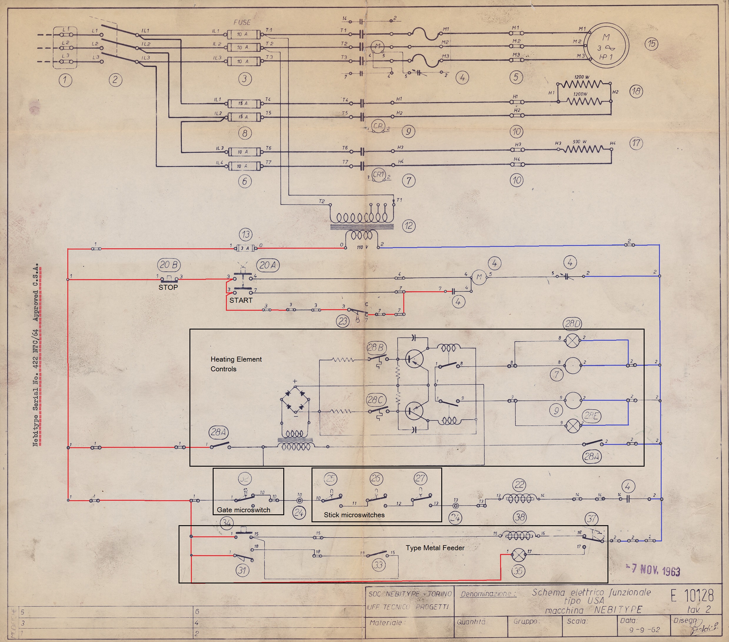
3-Phase Nebitype
The wiring diagram below shows a 3 Phase NTC with the motor being driven by three phase - presumably 120V.
The elements are all driven between 2 phases, at around 208V. The pot elements are between phases 1 and 2 while the mouthpiece element is between phases 2 and 3.
The control circuit is run from a step down transformer between phases 1 and 2. There may be a reason why the transformer isn't connected between the lighter loaded phase 2 & 3.
The transformer effectively isolates the control circuitry from the mains voltage - possibly as a safety measure.
Some simple colours and notes attached to this diagram. This is by no means complete (or guranteed to be safe or accurate to base any work on.)
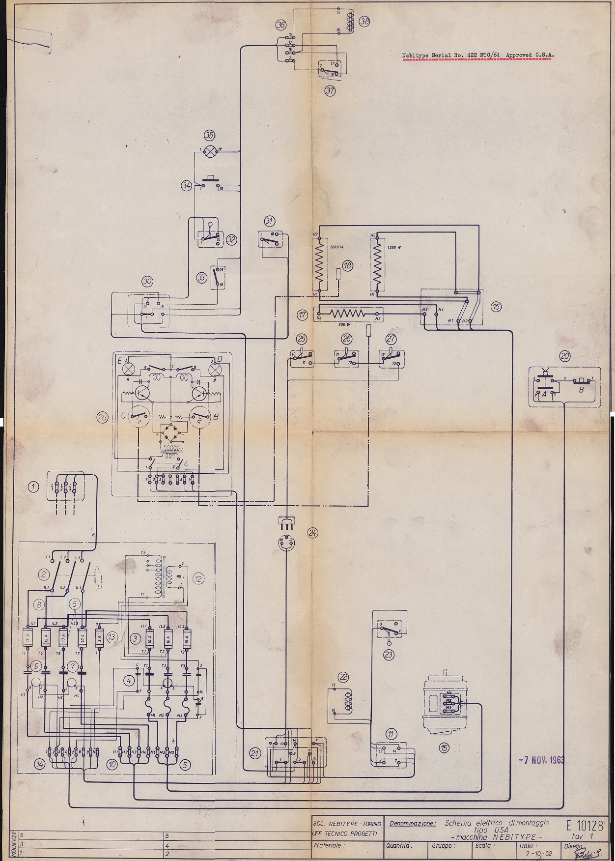
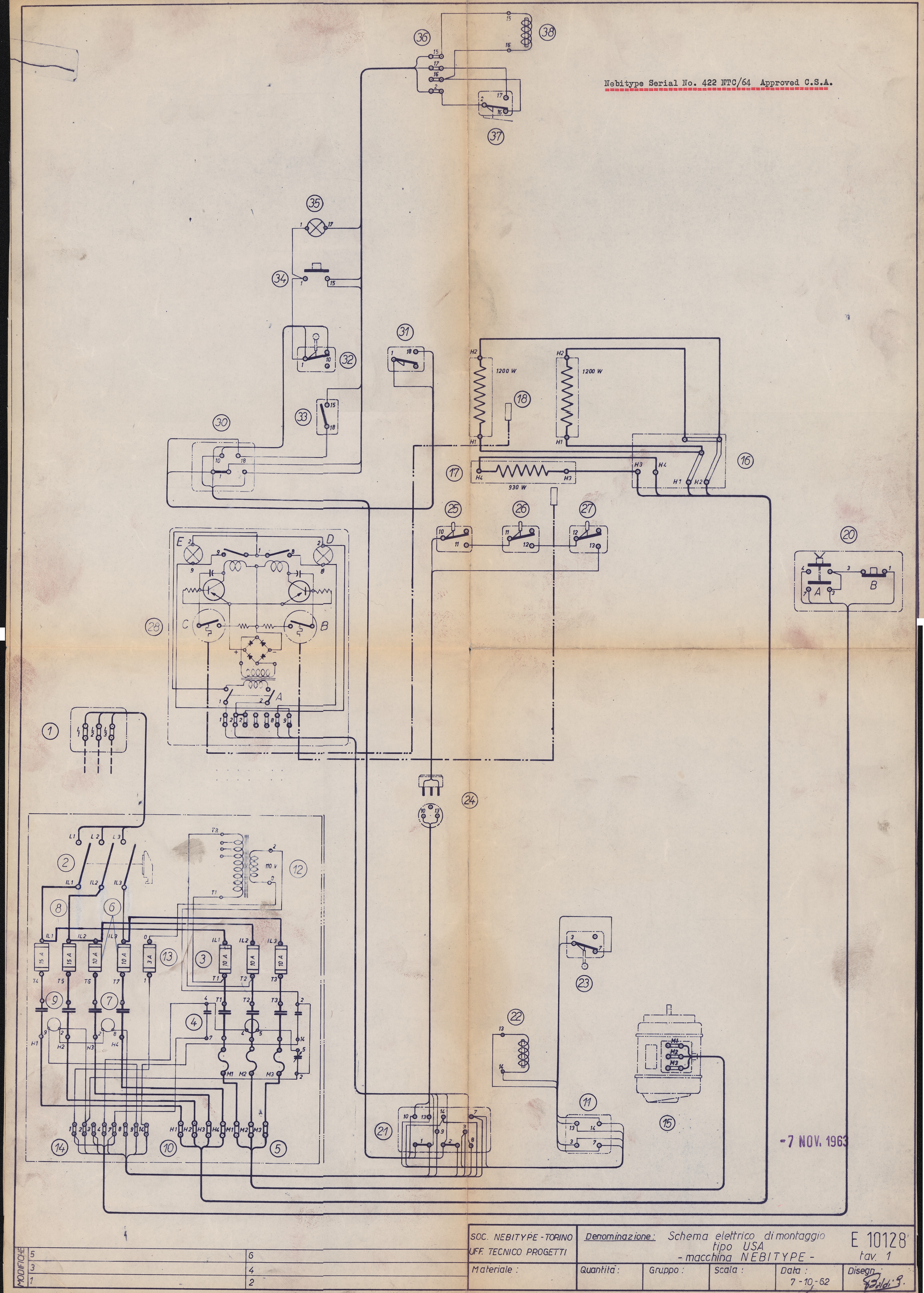
Another Diagram of a US 3 Phase machine
US Wiring Diagram - Tiny (120K)
US Wiring Diagram - Normal (709K)
US Wiring Diagram - Massive (9M)
Modifications
Microswitch assembly indicator lamp
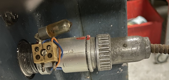
The NZ Printing Museum has an Ultra E model Nebitype with an intermediary plug/socket between the microswitch assembly plug and the body of the machine.
This plug has a small neon lamp inside it. My assumption is that if the Microswitch assembly circuit is not complete (i.e. one of the switches is open)
then the lamp will flash at the point in the cycle that the Nebitype energises the microswitches to verify that the stick is in position.
NOTE that the controller voltage is around 110V, which is likely why a NEON lamp is used as opposed to a small incandescent lamp.
This would give a visual indication that there is a fault with the stick positioning relative to the mouthpiece. The lamp would not light, however,
if the issue were to do with the protective cover microswitch.
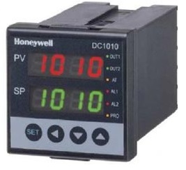
My NTC came with a PID controller instead of the standard pot heater controller. A PID controller, in combination with an appropriate thermocouple and a solid state relay will permit very accurate
control of a heating circuit. Some controllers can be programmed with a heating profile to apply heat in an optimised manner. PID controllers (with solid state relays) are fairly bulletproof, quiet and have a lot more options than a simple contactor circuit.
Ultra-E Wiring (pdf).
Pot Temperature Controller Instruction Manual (pdf).
A hand drawn sketch of some electrics found in my documentation...